Using the stripboard is not my favouite choice but it seems I am using it more and more. This is because it allows me to create a circuit fast but at the sacrifice of proper design, the size of the board (which should be smaller) and worse of all, lots of wires. Anyway, lets discuss about the stripboard for this project. Initially, I wanted the circuit board to be as flat as possible in case of last minute snafu. This is because of the toy's speaker's retaining clip which might interfere with the circuit board. So, the only way to do this is to solder the IC chip directly onto the board. This is not a good thing if you need to take it out and put it in again. And so, in keeping with standard practice, I used an IC socket instead of direct soldering. As space is at a premium in the board, I also soldered the resistors upright. Maybe I should have bought the 1/8 watt instead of the 1/4 watt which is half the size. Not only that, for other connections, I used the PCB headers. But for the power to the PCB board, I soldered it directly.
The reason why I am using PCB headers and upright resistors is that it is easier to solder those fragile wire-wrapping wires to them instead of flipping the board over and solder them underneath. The extra movement (translated to more than 14 times) would weaken some of the already soldered wires and also, if any of them comes off, it is very difficult to remove the board, and re-solder them again. This way, I just solder the ends of the wire to the tips.
|
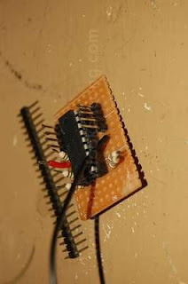
| Hmmm..... I don't understand why the picture turned out like this. But never mind. Here, you can see the board is starting to gain in height after I soldered an IC socket onto it. Once I added the chip itself, well, its very tall. With the PCB headers and the resistors, the board is now very big. Oh dear. |
This is a very important piece of the puzzle. Not only does it control the power to both circuits, its also gives you a wonderful headache if you're not careful. The green switch is basically just a lever switch or a micro switch. The main problem with this switch is that there is no space once you put in the LEDs. And so, that is why I need to push the last LED out a bit so that the switch might be able to fit in back to its original place. However, you might find that you need to reposition it a bit, maybe in a slanted fashion because the legs of the LEDs might affect its position. And not only that, it must be deep enough so that the two halves of the toy can be closed tightly. Still, anyway you out it, as long as the plastic lever on the flap is able to activate the switch, you're ok.
Wiring the circuit is very easy (i fyou have been practising your soldering skills, of course). What you need to do is to tin the PCB headers and the resistors first. I would not recommend you to tin the ends of the wires as the plastic will melt further and expose the wires which could start possible shorts. Once you're ready, just use the sharp tip of the soldering iron to melt the tinned solder and let the ends of the wires mix with the melted solder. Hold it for a few seconds for the solder to cool and solidify. If you have shaking hands, you might need something to hold the wires together because any movement when the solder is cooling, would cause a very bad solder join.
Don't you hate it when it happens? It came to me when I was wondering why the two halves of the Tricorder could not close. Try as I might, I could not get them to do it. At first, I thought it was because of the Tricorder's speaker assembly blocking my circuit board but it wa not so. Very much later, I discovered the some plastic parts on the other half, especially the ones across the small green flap switch, was themain culprit. And so, I cut them off. Then it hit me.......
 |
 |
 |
|
You can see a lot of wires inside the toy. During the test fit, it felt as if there is someting inside obstructing the two halves. And after much careful fiddling, the problem seems to be near the flap area.
|
Turns out to be the plastic tabs (1) and (2). And as soon as I removed them, I discovered something which I have very much overlooked. By removing them, I have more space!
|
When the plastic parts have been removed, there is, in theory, enough space to put a circuit board in there! But as long as I use a SMT chip, that is. Here is a sample of an SMT chip in the available space.
|


